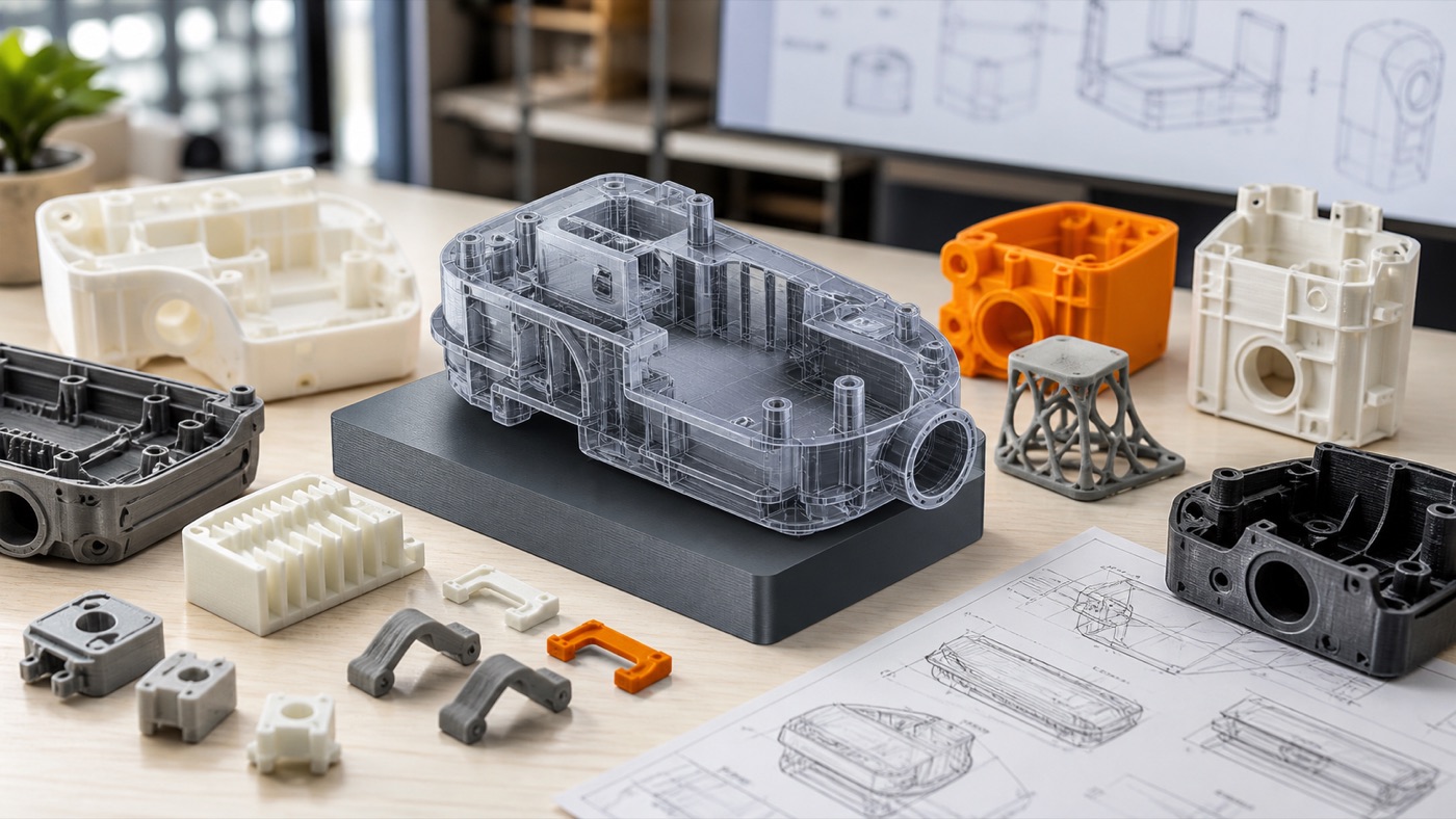
A small broken plastic component can make an otherwise useful product difficult or impossible to use. The frustrating part is that the replacement may no longer be sold, may take weeks to arrive or may only be available as part of a much larger assembly.
In some cases, 3D printed replacement parts offer another option. A damaged component can be measured, redesigned in CAD and manufactured as a new physical part. This is not suitable for every component, but for the right application it can be an extremely practical use of 3D printing.
What Types of Parts Can Be Recreated?
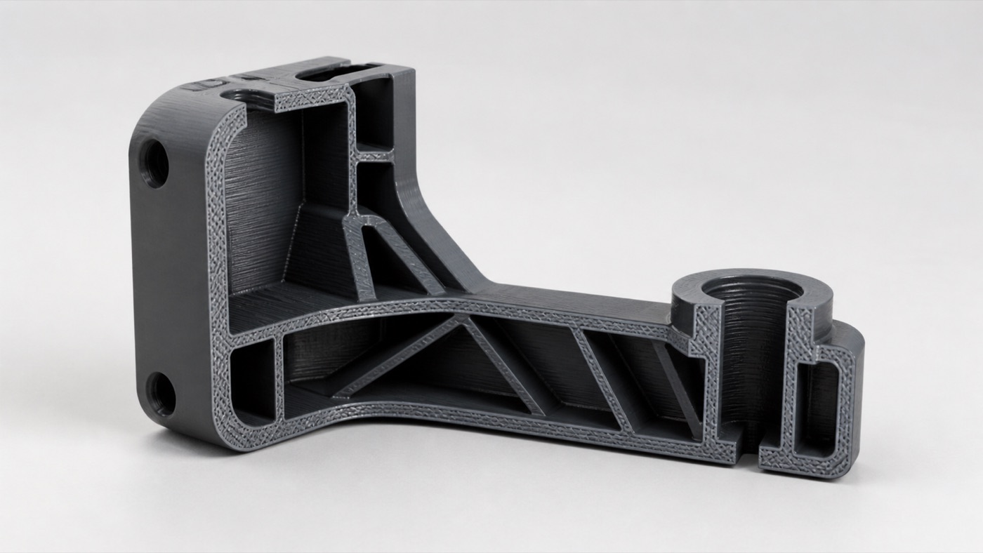
Examples can include knobs, covers, clips, spacers, brackets, holders, handles, housings, feet, guides and other non-critical plastic components. The best candidates have geometry that can be measured and a working environment compatible with available printing materials.
Safety-critical parts require much more caution. Components related to life safety, high loads, high temperatures, pressure systems or regulated equipment should not simply be copied without appropriate engineering validation.
Step 1: Understand Why the Original Part Failed
Before copying a broken part exactly, ask why it broke. Was a thin tab overloaded? Did a screw crack the plastic? Was the part exposed to heat? Did it fail after repeated bending?
If the failure mode is obvious, the redesigned part may be improved. A fillet can reduce a sharp stress concentration, a wall can be thickened or the print orientation can be chosen to better handle the expected force.
Step 2: Gather the Broken Pieces
Do not throw away fragments. Even a broken component contains useful dimensional information. Reassemble the pieces temporarily if possible and photograph the part from several angles.
Also photograph where the component fits in the larger product. The surrounding assembly can reveal which dimensions are truly critical.
Step 3: Measure Critical Dimensions
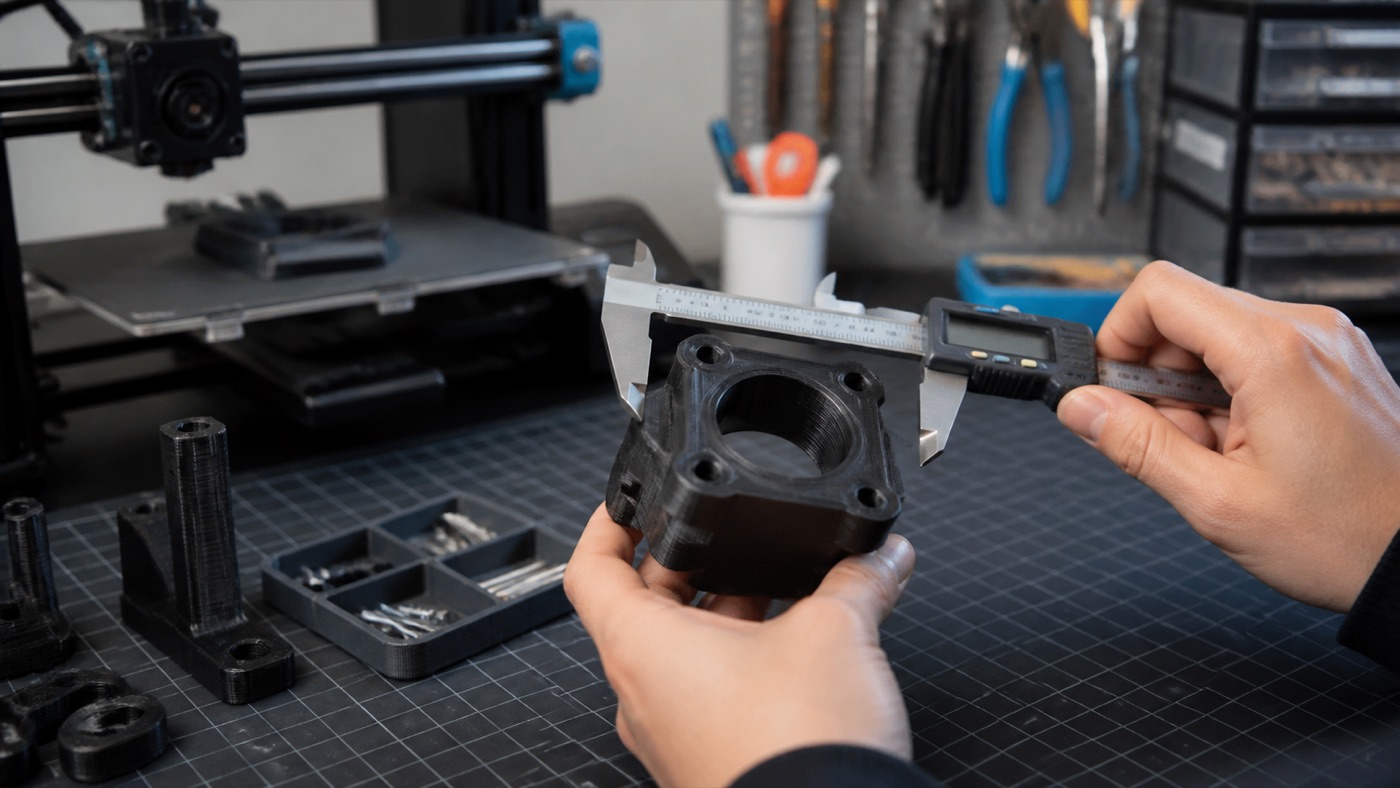
Digital calipers are extremely useful for reverse engineering. Measure overall length, width and height, hole diameters, distances between holes, wall thickness, shaft diameters and mating features.
Not every surface needs perfect measurement. Focus first on the geometry that controls fit and function.
Step 4: Rebuild the Part in CAD
A functional replacement is generally better created as a controlled CAD model than as a purely visual mesh. CAD allows dimensions, holes, clearances and features to be adjusted precisely.
If the original part is symmetrical, that can simplify reconstruction. If it interfaces with another component, model the mating geometry carefully.
Step 5: Add the Right Tolerances
A CAD hole with exactly the same nominal diameter as a shaft does not always produce the desired fit after printing. Manufacturing processes have tolerances. Sliding fits, press fits and screw clearances need appropriate allowance.
The best tolerance depends on the printer, material, orientation and feature size. For critical fits, a small test piece can be printed first.
Step 6: Choose Material Based on the Environment
PLA may work for a simple indoor knob or cover. PETG may be a better candidate for many functional parts that need additional toughness. TPU can replace certain flexible components. Other materials may be appropriate depending on heat, sunlight and mechanical requirements.
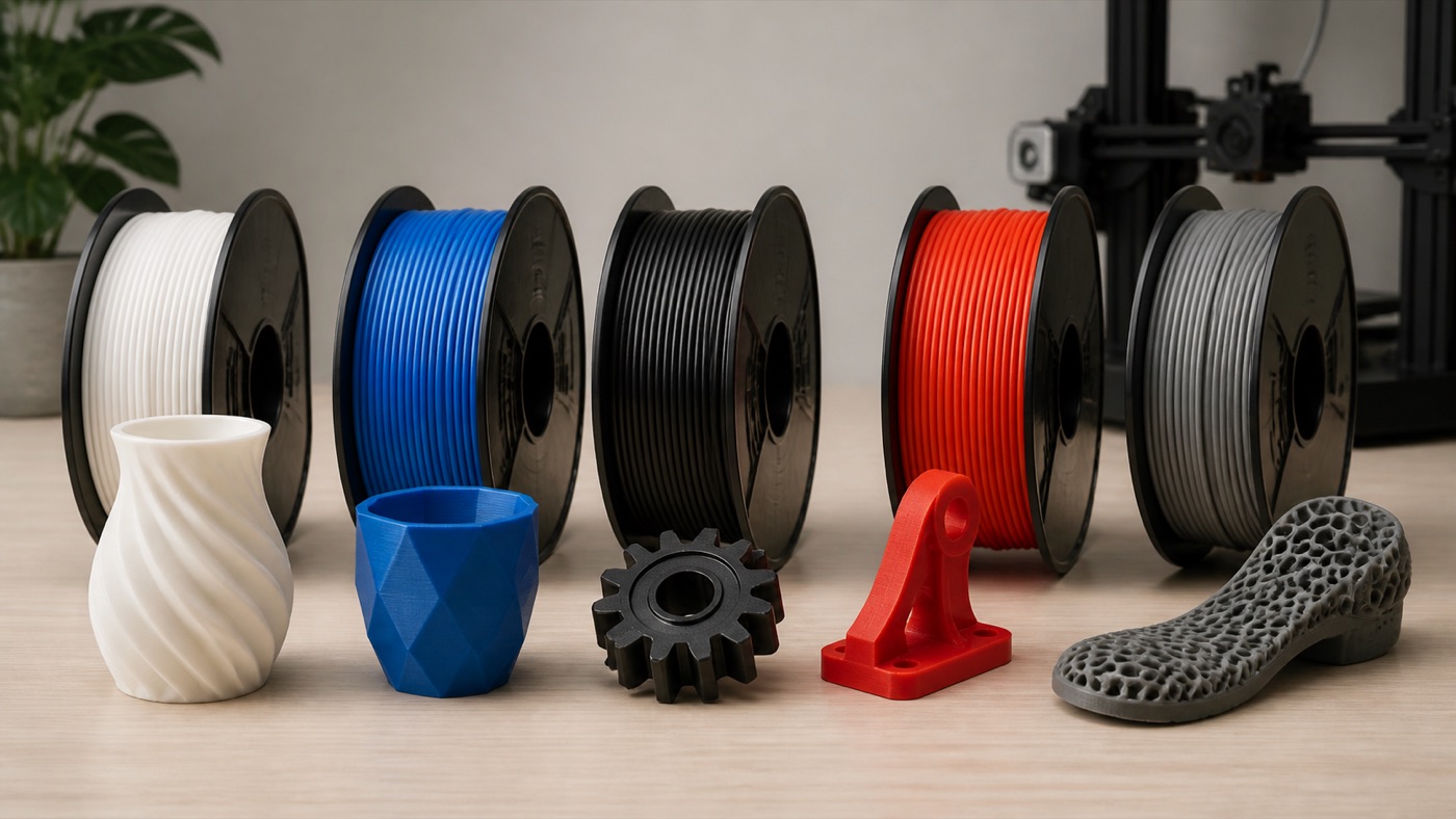
Do not assume that matching the original plastic is always possible or necessary. What matters is whether the new part meets the real working requirements.
Step 7: Think About Layer Orientation
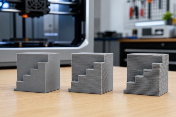
FDM parts are built layer by layer, which means orientation affects performance. A small clip printed in the wrong direction may separate along layer lines even if the material itself is strong.
During slicing, consider the direction of the main load and orient the part so the layer structure supports that load as effectively as possible.
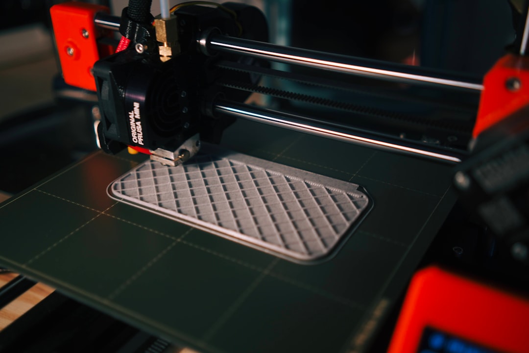
Step 8: Print and Test Version One
The first version should be treated as a prototype. Install it carefully and check fit before applying full load. Look for interference, excessive looseness or areas that are difficult to assemble.
If a hole is slightly misplaced or a clip needs more clearance, change the CAD model and print the next version. This is often faster than trying to force a flawed part to work.
Can You Make a Replacement From Photos Only?
Photos can help, especially when they include a ruler or known reference dimension, but they are rarely as reliable as direct measurements. Perspective distortion makes exact dimensions difficult to infer from a single image.
For the best result, provide the physical broken part or detailed measurements whenever possible.
What About Scanning?
3D scanning can be useful for organic or complicated surfaces, but it is not automatically the best method for every mechanical part. Simple geometric components can often be recreated more cleanly in CAD from measurements. Scanned meshes may still require cleanup and redesign before printing.
When 3D Printing Is Not the Right Solution
Do not use an unvalidated printed replacement where failure could cause serious injury, electrical hazards or major equipment damage. Very high temperatures, extreme loads and certain chemical environments may also require a different manufacturing process or certified material.
3D printing is a tool, not a universal replacement for every industrial process.
Recreate a Custom Part With Artin3D
Artin3D works on custom design, reverse-engineering style projects and FDM/SLA printing. If you have a broken or unavailable component, send clear photos and dimensions and explain where the part is used.
When appropriate, the component can be redesigned, prototyped and tested until the fit is right.
Artin3D – Where ideas take shape.