Accurate measurement is the foundation of reverse engineering. A CAD model can look identical to a physical object on screen and still fail if a mounting hole is one millimeter out of position. When a 3D-printed part must fit existing hardware, measurements should be collected systematically rather than guessed from photographs.

Decide what must be accurate
Before measuring, understand the part’s function. A decorative surface may tolerate small differences, while a bearing seat or PCB mounting pattern may not. Mark critical interfaces first so your effort goes where it matters.
Basic measurement tools
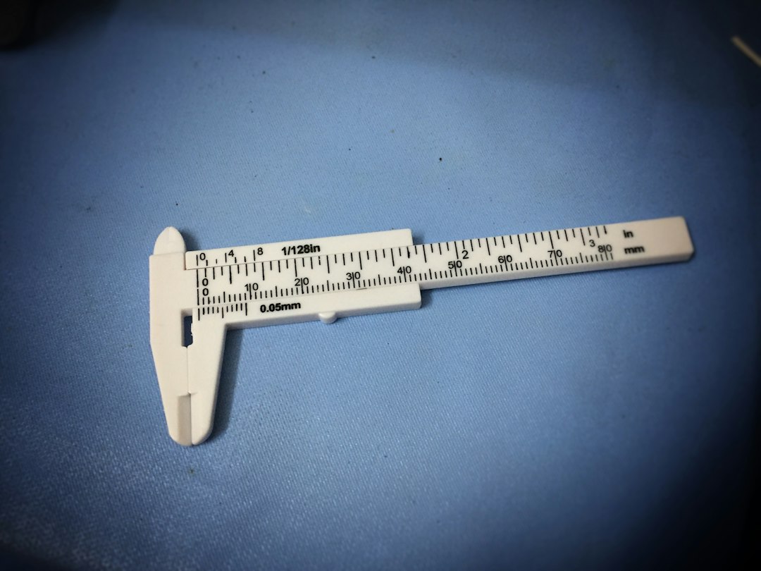
- Digital caliper for small dimensions
- Steel ruler for larger lengths
- Micrometer when suitable precision is required
- Radius gauges or reference templates
- Angle gauge
- Thread gauge where appropriate
- Flat reference surface
Create a datum
A datum is a reference from which other measurements are located. Instead of measuring every feature from a different edge, choose stable surfaces and establish a consistent coordinate system. This reduces accumulated errors.

Measure overall dimensions first
Record maximum length, width and height. These dimensions provide a bounding box and help detect mistakes later. If the CAD suddenly exceeds the measured envelope, revisit the sketches.
Measure holes correctly
For mounting holes, diameter alone is not enough. Record center-to-center spacing and the position relative to your datums. When direct center measurement is difficult, measure between edges and calculate the center distance.
Measure wall thickness
Wall thickness affects strength, fit and printability. Measure accessible edges at multiple locations because molded products may not have perfectly uniform walls.
Measure shafts, slots and pockets
Identify whether a feature is intended to slide, rotate, press-fit or remain fixed. That function determines the clearance needed in the new CAD.

Do not confuse nominal size with printed size
A CAD hole modeled at 5.00 mm may not print as an exact 5.00 mm hole. Printer calibration, material shrinkage, orientation and process characteristics influence the physical result. Use test pieces when a fit is critical.
Handling curves
Curved surfaces are harder than simple prismatic geometry. Measure several points along the profile rather than assuming one radius. For organic shapes, photographs, tracing, scanning or photogrammetry can supplement direct measurements.
Use symmetry
If a broken object is symmetric and one side survives, measure the intact side and mirror it in CAD. Confirm the actual product was intended to be symmetric before relying on this method.
Measure repeated patterns
For a row of holes or vents, measure the total pattern length and individual pitch. Repeated features are easier to build parametrically in CAD and can reveal measurement inconsistencies.
Record everything immediately
Write each dimension on a sketch or photograph as you measure it. Avoid relying on memory. Use consistent units and identify whether values are measured, calculated or estimated.

Measure mating components too
If you are designing an enclosure for a PCB, measure the board but also the connectors and wires. If a replacement fits a shaft, measure the shaft itself rather than only the damaged hole.
Account for screw heads and tools
A screw hole may be perfectly positioned yet impossible to assemble if there is no space for the screw head or screwdriver. Measure the complete assembly envelope.
Thread identification
Determine whether the original uses a machine screw, self-tapping screw or molded thread. When uncertain, bring the actual fastener with the part. Printed designs may be adapted to use inserts or nuts rather than reproducing a tiny original thread.
Complex internal geometry
Internal channels and hidden ribs can be difficult to measure. If they do not affect function, simplification may be better than trying to reproduce them exactly. Preserve interfaces and structural requirements first.
Photograph the measurement process
Photos showing caliper placement can clarify what a dimension represents. Capture front, back, left, right, top and bottom views before modeling.
When scanning is useful
Scanning is valuable for complex organic surfaces, but raw mesh data is not a substitute for controlled dimensions on mechanical features. A hybrid workflow can use scan data for shape and parametric CAD for holes, mounting faces and other interfaces.

Build the CAD in a logical order
- Create the main reference planes.
- Build the primary volume.
- Add critical mounting geometry.
- Add pockets, holes and slots.
- Add secondary ribs and details.
- Add fillets and cosmetic features last.
Cross-check the model
Measure the CAD model digitally and compare it with your original notes. Check overall dimensions and several independent feature distances. This catches transcription errors before printing.
Print targeted test pieces
If only one interface is uncertain, print that region instead of the entire object. A small test containing a bearing seat or connector opening can save material and hours of machine time.
Fit categories
Think about whether the connection should be loose, sliding, snug, press-fit or fixed with a fastener. There is no universal clearance for all printers and materials, so calibration tests and experience matter.
Common measurement mistakes
- Measuring from damaged edges
- Mixing millimeters and inches
- Ignoring mating components
- Rounding dimensions too early
- Assuming symmetry without checking
- Measuring hole edges but forgetting center position
- Ignoring tool access
- Trying to infer depth from a single photo
Checklist before modeling
- Overall dimensions recorded
- Datums identified
- Critical interfaces marked
- Hole sizes and locations measured
- Wall thickness checked
- Fasteners identified
- Mating components measured
- Photos captured from multiple angles
- Uncertain dimensions clearly marked for testing
Conclusion
Reliable reverse engineering begins with disciplined measurement. Establish datums, prioritize functional interfaces, record dimensions clearly and validate uncertain fits with targeted prototypes. Artin3D can work with suitable physical components, measurements and client references to create printable CAD and test parts for custom projects. Artin3D – Where ideas take shape.