A broken plastic part can make an otherwise useful device difficult to repair, especially when the original spare is unavailable. Reverse engineering provides a practical route: study the surviving component, measure its critical features, rebuild the geometry in CAD and test a 3D-printed replacement.
What reverse engineering means
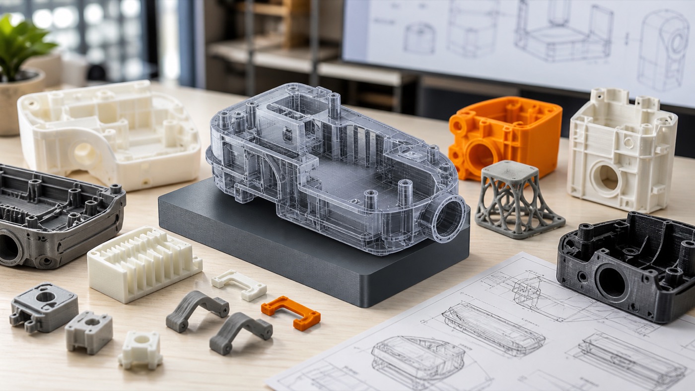
For this type of project, reverse engineering means reconstructing the functional geometry of an existing physical part when the original digital model is unavailable. The goal may be an accurate replacement or an improved version that preserves fit while correcting a weakness.
Which broken parts are good candidates?
- Plastic covers and housings
- Knobs and handles
- Mounting brackets
- Clips and guides
- Equipment feet
- Electronic enclosures
- Custom holders
- Low-load gears or mechanisms where appropriate
- RC and hobby components
- Obsolete plastic accessories
Step 1: keep every broken piece
Do not throw away fragments. Even a cracked section can reveal original wall thickness, curvature, hole location or snap geometry. Photograph the component before attempting repairs so the designer can understand how it failed.
Step 2: understand what the part connects to
The mating product is often as important as the broken part. A bracket may need to align with holes in a machine; an enclosure may need to fit a PCB; a knob may need a specific shaft profile. Whenever possible, provide the related hardware.
Step 3: identify critical dimensions
Not every dimension requires the same precision. Mark the features that control fit and function.
- Hole diameter
- Hole-to-hole distance
- Shaft diameter
- Slot width
- Bearing seat
- Overall envelope
- Clip engagement
- Mounting-face position
Step 4: measure the geometry
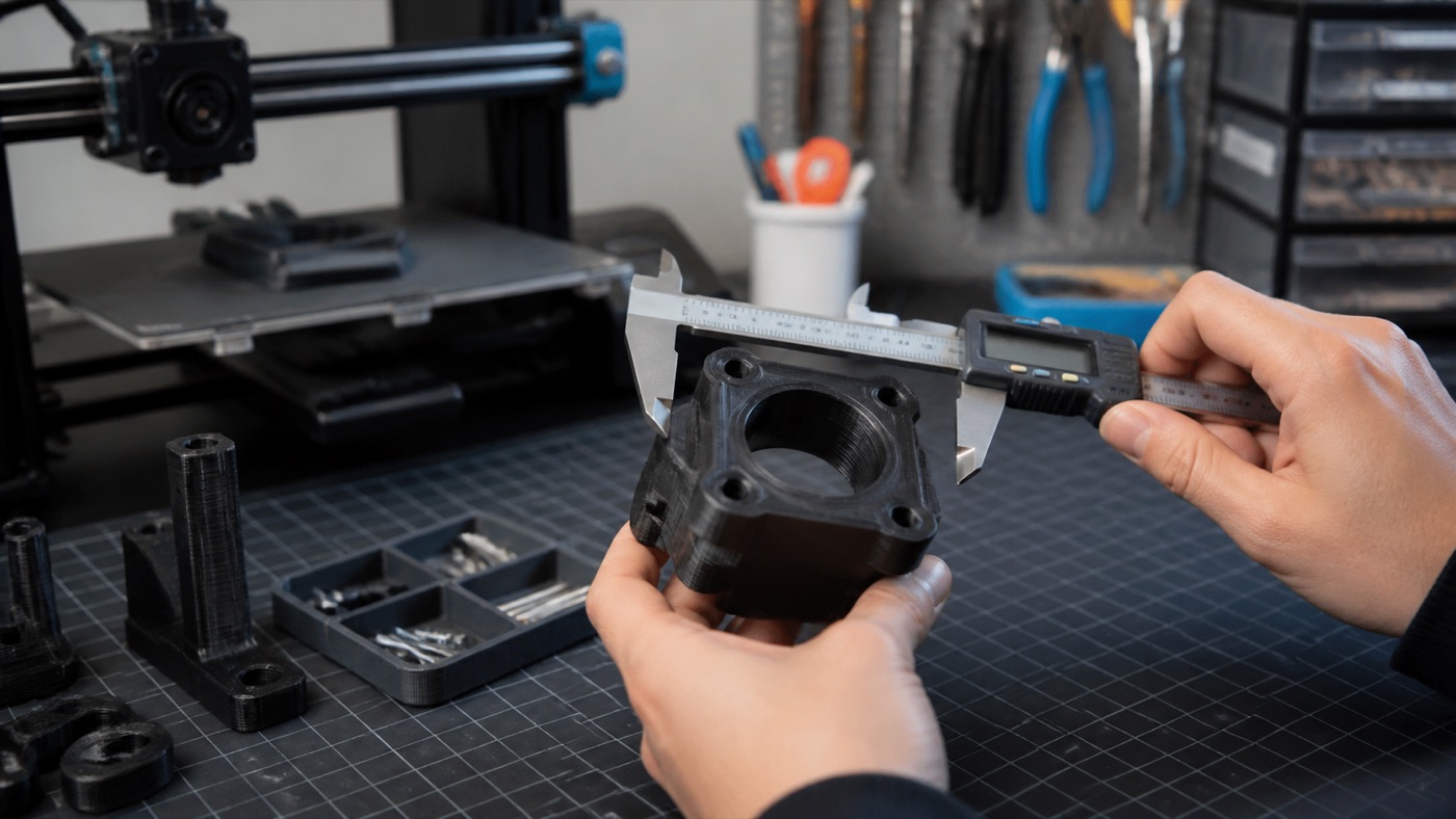
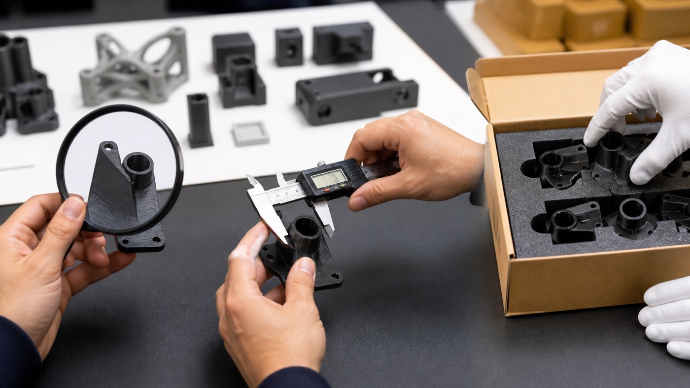
Digital calipers are useful for many small mechanical parts. Rulers can help with larger overall dimensions, but critical interfaces deserve more precise measurement. Complex curves may require reference templates, scanning or iterative test fitting.
Step 5: rebuild the CAD
The designer creates sketches and solid features based on measurements. Symmetry and repeated features can help reconstruct missing areas. If one side is intact and the other is broken, the surviving geometry may provide enough information to mirror the design.
Should the new part be an exact copy?
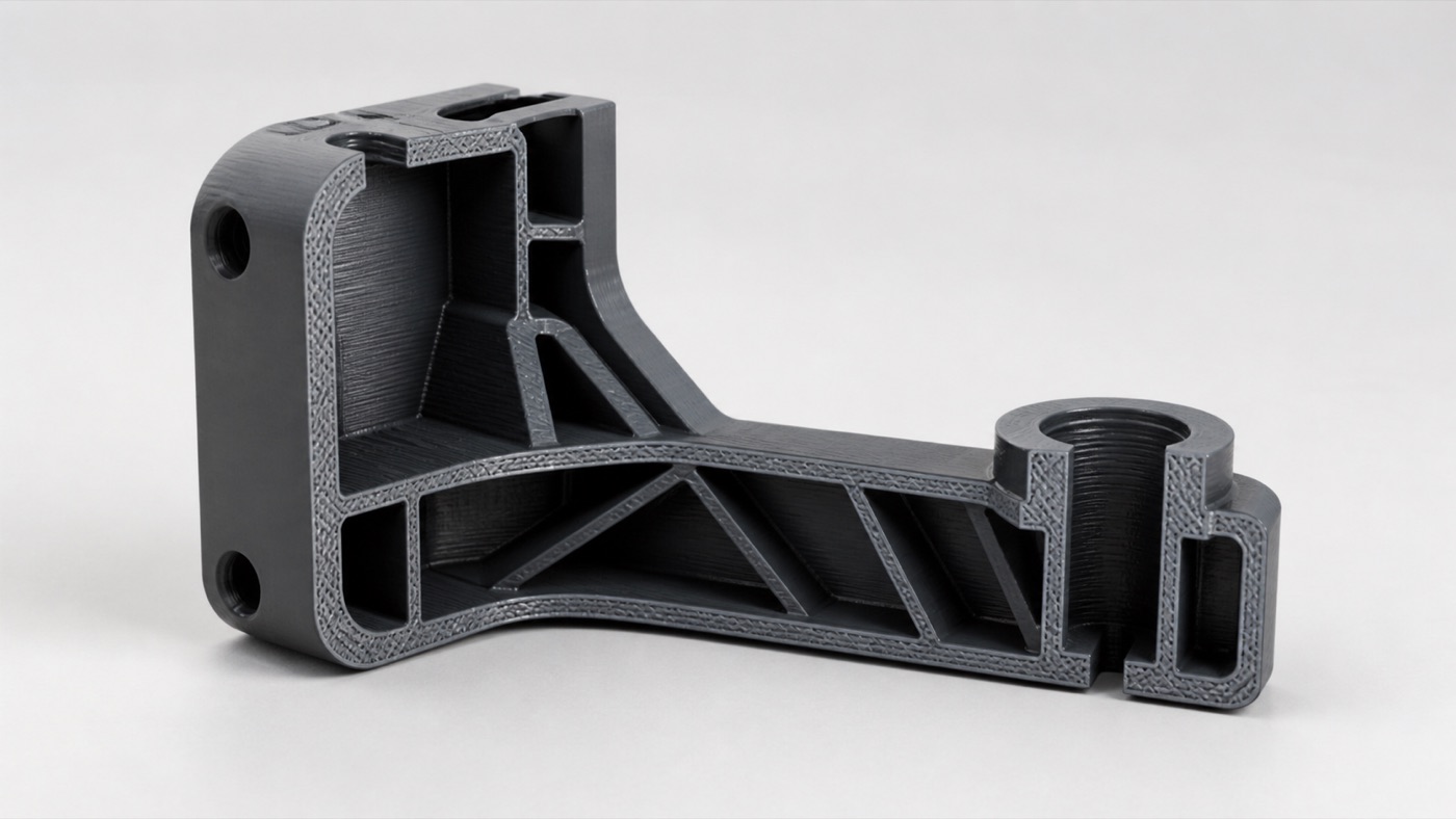
Not always. If the original failed because a screw boss was thin or a corner created a stress concentration, the replacement may benefit from reinforcement. Any modification must preserve required clearance and assembly.
Possible improvements include:
- Thicker walls in non-interfering areas
- Fillets around stressed corners
- More material around screw bosses
- Heat-set insert features
- Improved cable clearance
- Better print orientation through redesign
Step 6: choose the printing material
The original material does not automatically dictate the printed material. The replacement should be selected according to heat, flexibility, impact, UV exposure and load.
PLA can be useful for prototypes and many indoor parts. PETG can suit tougher functional uses. ABS or ASA may be considered for higher-temperature requirements, and TPU is appropriate when flexibility is intentional.
Step 7: plan print orientation
FDM parts are built in layers, so orientation affects strength and surface quality. A replacement bracket should be oriented so important loads are considered rather than choosing orientation only for appearance.
Step 8: print a prototype
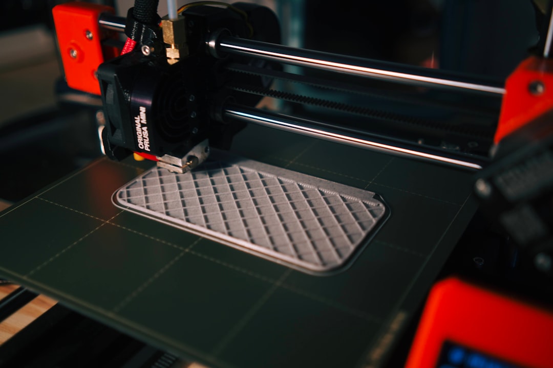
The first version should validate dimensions. If only one feature is uncertain, it may be efficient to print a small test section instead of the entire component.
Step 9: test fit carefully
Do not force a prototype into place. Check alignment and measure the discrepancy. A fit issue can result from CAD dimensions, printing variation or incorrect assumptions about the original geometry.
Step 10: revise and print the final part
Update the CAD based on measured test results. Once fit is confirmed, produce the final version using the intended material and quality settings.
When scanning helps
3D scanning can capture complex surfaces, but scan data still needs cleanup and scale verification. For mechanical interfaces, measured CAD features may be more useful than relying entirely on a raw mesh.
When photos help
Photos are excellent references for shape and assembly context. Take images from front, back, left, right, top and bottom. Include close-ups of damaged areas and mounting features. A ruler in the frame can provide scale reference, although direct measurements are better.
Why one image is risky
A single perspective image hides depth and introduces lens distortion. The designer cannot know the exact rear geometry or internal structure. More views and dimensions significantly improve reconstruction quality.
Tolerances matter
A hole modeled at the exact nominal diameter of a shaft may not produce the desired real-world fit. Printing has dimensional variation. Prototype testing is the safest way to establish clearance for a particular part and process.
What if the original is badly damaged?
Related components, symmetry, photographs and functional requirements can help infer missing geometry. Sometimes the better approach is to design a new compatible part rather than reconstruct every cosmetic detail of the original.
Replacement part versus original manufacturing
A 3D-printed replacement may not have exactly the same material properties or surface finish as an injection-molded original. The design should therefore be adapted to the additive process where necessary.
Cost factors
A reverse-engineered project includes both design and manufacturing. Cost can be influenced by:
- Measurement complexity
- Missing geometry
- Number of mating components
- CAD time
- Prototype iterations
- Material
- Print time
- Finishing
- Quantity
How clients can make the process faster
- Send the original part.
- Include all broken fragments.
- Provide the mating hardware.
- Explain exactly where it failed.
- State operating temperature and environment.
- Identify critical dimensions.
- Allow a prototype-fit stage.
Safety considerations
Not every component should be reproduced casually. Safety-critical, high-load, high-temperature or regulated applications require appropriate engineering validation and material knowledge. A printed replacement should be evaluated according to the consequences of failure.
Typical workflow at a custom 3D printing service
- Inspect the part.
- Measure critical geometry.
- Create CAD.
- Review printability.
- Choose material.
- Print a test.
- Check fit.
- Revise.
- Print the final version.
- Keep the digital model for future replacements.
Conclusion
Reverse engineering can give unavailable plastic parts a practical second life. The most reliable process combines physical measurement, CAD reconstruction, material selection and prototype testing. Artin3D can evaluate suitable client components for custom design and FDM or SLA printing, depending on the project requirements. Artin3D – Where ideas take shape.