বেড ক্লিপ বসালে প্রিন্টের ব্যবহারযোগ্য জায়গা মাপা নিয়ে এই গাইড। আপনার প্রিন্টারের মডেল ও প্লেটের ধরন মিলিয়ে নিতে নিচে সংশ্লিষ্ট পণ্যের লিংক দেওয়া আছে।
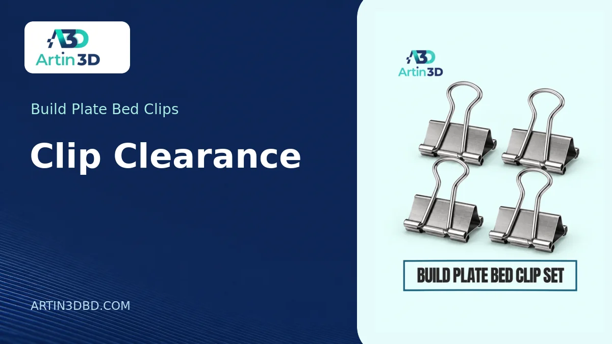
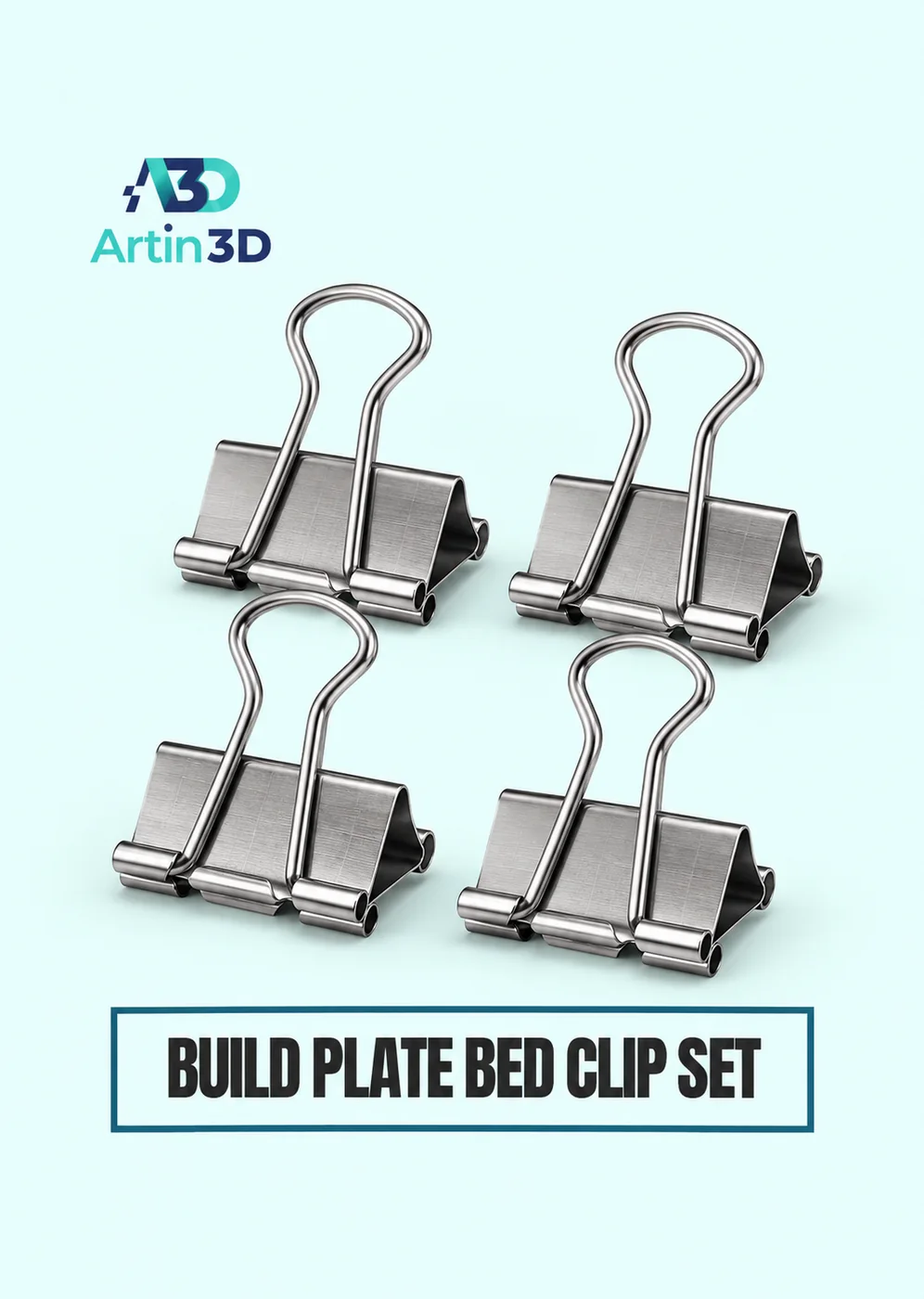
A build plate bed clip occupies more space than its jaws suggest. Its handles can extend inward over the printing area or outward into the path of a moving part. Before planning a large model on a printer that explicitly supports clips, make a clearance map for the approved clip positions. The number printed as the nominal bed width is only the starting point for this check. The printer’s own instructions determine whether external clips belong on the machine at all.
View Product · Build Plate Bed Clips
Identify the approved mounting locations
Look up the instructions for the exact printer and bed assembly. Check whether the manufacturer specifies a clip type, mounting points and handle position. A magnetic or specialised locating system may have no provision for an added clip. If the setup is undocumented, ask the printer supplier before fitting hardware. A clip that holds a loose sheet tightly on a desk has not yet proved suitable for a moving printer.
Trace what the clip actually occupies
With the machine cool and idle, use a paper outline the size of the plate. Place a sample clip on a separate piece of material of the intended thickness to understand its footprint. Transfer the inside reach of the jaws and handles onto the drawing. Mark the orientation of the front of the printer and the locations permitted by the manual. A side view helps show why an overhanging handle can occupy space at more than one height.
Include more than the model outline
Open the intended job in the slicer. Inspect the object, brim, skirt and any purge structures that appear on the first layers. Compare their occupied area with your drawing. Startup routines, wiping, probing and homing may follow additional paths outside the model outline. A slicer preview alone cannot establish clearance for those routines. Use the manufacturer’s documented movement restrictions and keep the hardware within the approved arrangement.
Think through a wide print
Suppose the model footprint is 180 mm and a brim extends 5 mm on each side. The occupied width becomes 190 mm before any separate skirt or other structure is counted. A part can therefore fit between two marks on paper while its brim crosses one. Moving the model or rotating it may give adequate clearance in a documented setup. Reducing a brim should be considered only if the revised print still meets the adhesion needs of the part.
Make the approved setup easy to repeat
Record a photograph from above with the printer idle, plus a side photograph showing the handles. Store those photos with the printer profile name and the paper drawing. Use a separate record for a different sheet thickness or clip design. Before each job, compare the physical arrangement with the approved example. Avoid reaching into a moving machine to adjust a clip or to investigate a possible collision.
Decide when a different plate is simpler
If a regular job repeatedly extends into a restricted area, identify a supported plate or retention arrangement with the needed usable area. For a purchasing enquiry, send the printer model, plate dimensions, thickness and the intended part footprint. Those four details make the discussion more useful than asking whether a generic clip will fit. Keep the final drawing at the workstation so the next operator can inspect a large layout before the printer starts.
Artin3D | Where Ideas Take Shape.
WhatsApp or Call +880 1845 348757
www.artin3dbd.com
South Banasree Dhaka 1219