
Turning a photo or real object into a 3D model sounds simple, but the best method depends on what you are trying to reproduce. A single image can show appearance, yet it cannot reveal every hidden dimension. A real object can be measured or scanned, while a logo or flat artwork may be reconstructed from its outline. For a successful 3D print, the goal is not merely to create something that looks three-dimensional on screen; the final model must also have correct scale, solid geometry, printable wall thickness and suitable details.
First decide what kind of source you have
Before choosing software, identify the information available. Different sources require different workflows.
- One photo: useful for visual reference, but hidden dimensions must be estimated.
- Multiple photos: better for reconstructing shape and proportions.
- A physical object: can be measured manually or scanned.
- A drawing with dimensions: excellent for accurate CAD reconstruction.
- A logo or silhouette: can often be traced and extruded.
- A broken part: may be reverse engineered using measurements and surviving geometry.
Method 1: manual CAD modeling from photos
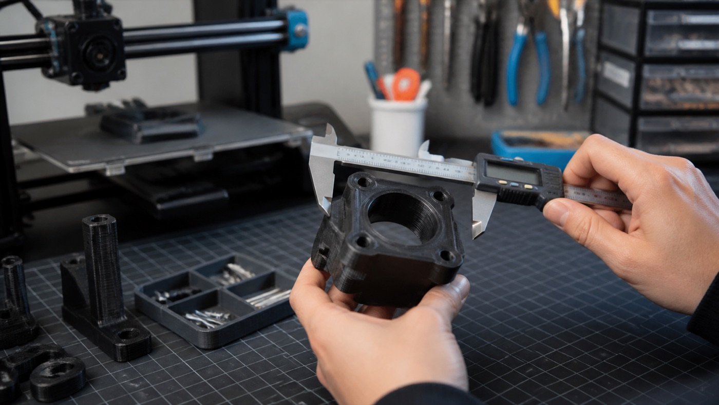
Manual CAD is often the most reliable method for functional products. The designer imports reference images, identifies known dimensions and rebuilds the geometry using sketches, extrusions, revolutions, fillets and other CAD features. This approach takes more skill than automatic image-to-3D conversion, but it gives control over dimensions and manufacturability.
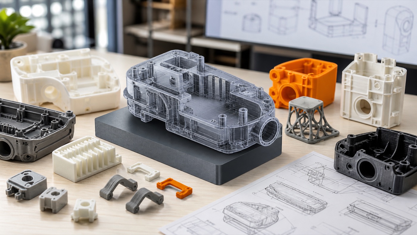
For example, if you need a replacement plastic cover, a photograph can help show the outer form while caliper measurements define hole positions, wall thickness and mounting features. The resulting CAD model can be designed specifically for FDM or SLA printing rather than merely copying the visible surface.
Method 2: photogrammetry
Photogrammetry uses many overlapping photographs taken around an object. Software identifies common visual features and estimates camera positions to reconstruct a 3D surface. It can be useful for sculptures, organic shapes, people, terrain and objects that are difficult to measure manually.
For better results:
- Use soft, even lighting.
- Keep the entire object sharp.
- Take photographs from several heights.
- Maintain strong overlap between neighboring images.
- Avoid moving the object between shots.
- Avoid reflective, transparent or featureless surfaces when possible.
- Include a known measurement so the final model can be scaled correctly.
Photogrammetry often creates a dense mesh that still needs cleanup. Holes may need filling, the bottom may need flattening and thin details may need reinforcement before printing.
Method 3: 3D scanning
A dedicated 3D scanner captures surface geometry directly. Depending on the scanner, object size and surface, this can provide useful dimensional information quickly. Scanning is especially valuable for complex organic geometry that would take a long time to model manually.
However, a scan is not automatically a production-ready CAD model. Scan meshes can contain noise and millions of triangles. Functional reverse engineering may require rebuilding important surfaces parametrically so dimensions, holes and mating features can be edited accurately.
Method 4: AI image-to-3D tools
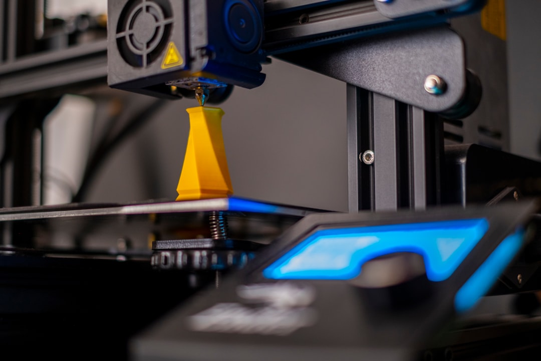
AI tools can generate a 3D-looking mesh from one or more images. They are useful for concept exploration, figurines and decorative subjects, especially when exact engineering dimensions are not required. They can dramatically reduce the time needed to obtain a starting mesh.
But an AI-generated model should be inspected before printing. Common issues include:
- Incorrect hidden-side geometry.
- Soft or invented details.
- Disconnected mesh sections.
- Thin areas that cannot print reliably.
- Wrong scale.
- Unwanted textures represented as geometry.
- Asymmetry that was not present in the original object.
For functional parts, AI should usually be treated as a starting point rather than a substitute for measurement and engineering CAD.
Method 5: converting a logo or 2D artwork
Flat artwork is one of the easiest image-to-3D tasks. A clean logo can be converted to vector paths, imported into CAD and extruded to a chosen thickness. This workflow works well for signs, badges, keychains, stamps, wall art and branded display pieces.
Before extrusion, simplify tiny features. Very narrow lines may disappear at small scale. If the design will be printed in multiple colors, separate color regions into distinct bodies or layers depending on the printer and intended workflow.
Why one photo is not enough for accurate engineering parts
A photograph is a perspective projection. Dimensions farther from the camera appear smaller, and the lens can introduce distortion. Without a known scale reference, software cannot know whether an object is 20 mm or 200 mm wide. Hidden features are completely unknown.
If accuracy matters, provide:
- Front, back, left, right, top and bottom photos.
- At least one known dimension.
- Close-ups of mounting features.
- Caliper measurements of holes and slots.
- Photos with a ruler when precise tools are unavailable.
- The physical object when practical.
Scale the model correctly
Even an excellent mesh is useless for a replacement part if it is the wrong size. CAD software generally works in defined units, but STL files historically store geometry without an explicit unit declaration. Confirm whether the model is intended to be interpreted in millimeters and verify overall dimensions before slicing.
Make the mesh printable
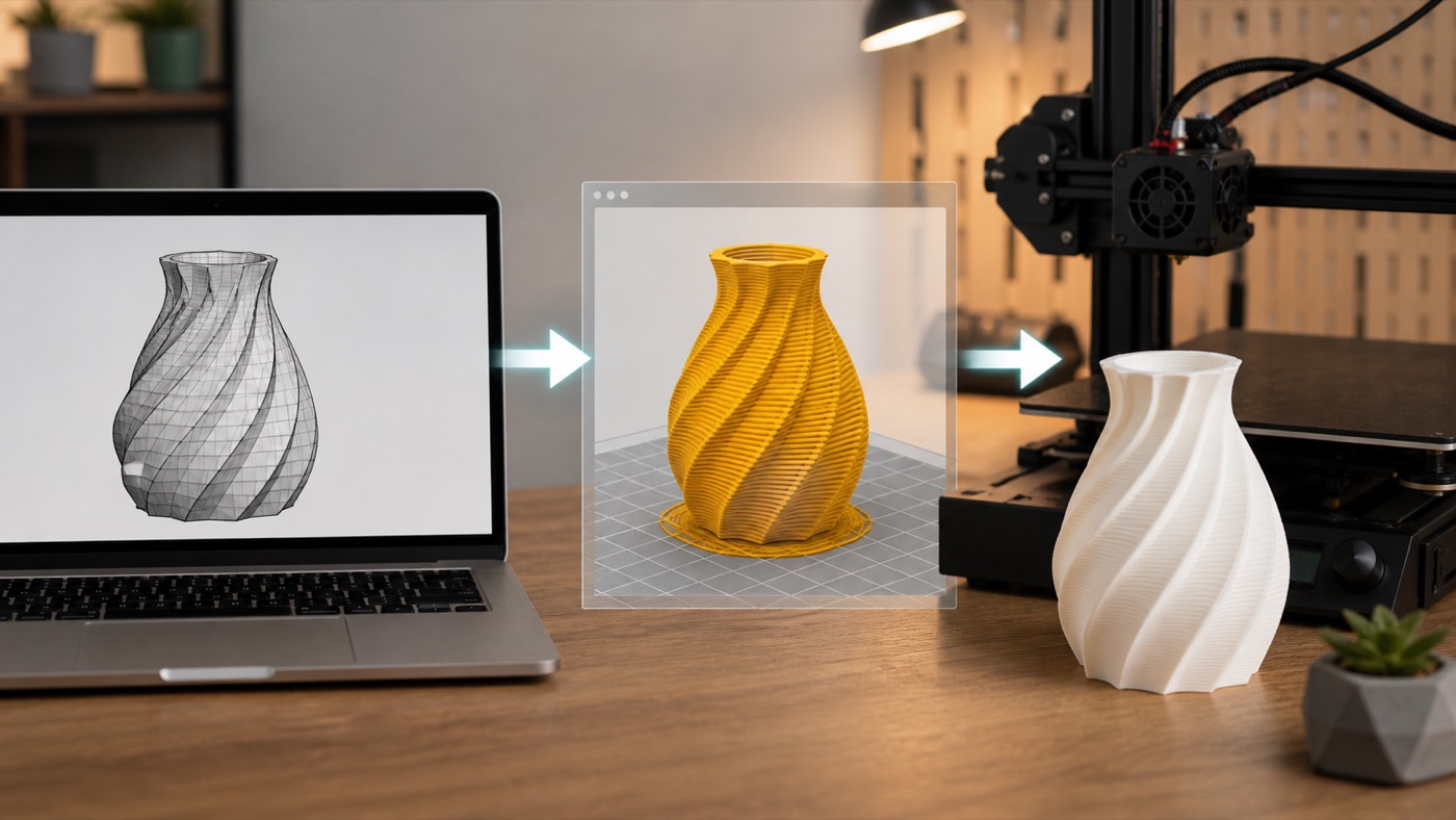
A visual 3D model can contain surfaces that have no physical thickness, intersecting geometry or open edges. A printable model should generally represent a closed solid volume.
Check the following:
- Is the mesh watertight?
- Are normals facing correctly?
- Are there non-manifold edges?
- Are all components connected where they should be?
- Do thin walls meet the printer’s practical limits?
- Are tiny floating details necessary?
- Can supports be removed after printing?
Choose FDM or resin based on the model
FDM is often appropriate for larger functional objects, enclosures, brackets, prototypes and many everyday products. SLA/resin printing is useful when small detail and a smoother-looking surface are priorities. A scanned statue may benefit from resin at miniature scale, while a reconstructed machine cover may be more practical in FDM.
Design changes may improve the reproduced object
Reverse engineering does not always mean making an exact copy. If the original part broke around a thin screw boss, the new model can potentially add a fillet or reinforce that area. If an old enclosure had poor cable access, the reconstructed design can be improved.
Useful modifications include:
- Thicker weak sections.
- Rounded stress concentrations.
- Heat-set insert pockets.
- Better ventilation.
- Improved cable routing.
- Updated mounting holes.
- Alignment pins for assembly.
Prototype before producing quantity
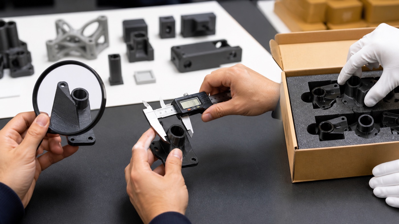
Print one test piece first when fit matters. Install it on the real product and check every interface. A model can be visually accurate yet miss a screw position by a fraction of a millimeter. Small corrections are inexpensive before batch production.
Which workflow should you choose?
- Logo or text: vector tracing and extrusion.
- Simple mechanical part: manual measurements and CAD.
- Complex mechanical part: scanning plus CAD reconstruction.
- Statue or organic object: photogrammetry or scanning.
- Decorative concept from one image: AI image-to-3D plus mesh cleanup.
- Replacement component: measurement-focused reverse engineering.
What to send to Artin3D
If you want a real object converted into a printable model, send clear photographs and explain what the finished print must do. Include dimensions and the physical component when possible. If the new part must fit a PCB, camera, bearing, motor or other object, those interfaces are more important than purely visual similarity.
For image-based decorative models, send the highest-quality reference available. Multiple angles produce better information than a single front image. State the desired final height or width so the model can be prepared at a useful scale.
Final checklist
- Choose the reconstruction method based on the source.
- Collect enough reference images.
- Record at least one reliable dimension.
- Rebuild critical functional geometry accurately.
- Repair the mesh before slicing.
- Set final scale deliberately.
- Choose FDM or SLA according to detail and function.
- Print a test before committing to quantity.
Conclusion
Converting a photo or object into a 3D model is not one single process. AI, photogrammetry and scanning are excellent tools for capturing shape, while CAD is often the better route when dimensions and mechanical fit matter. The most reliable workflow combines good reference information with a model designed for the actual printing process. Artin3D can work from client photos, measurements, components and existing digital files for suitable custom modeling and 3D printing projects. Artin3D – Where ideas take shape.