Making a custom case for a PCB, Arduino or Raspberry Pi is one of the most useful applications of 3D printing. Off-the-shelf cases work when the electronics stay standard, but projects quickly become unique when you add a display, camera, custom sensor, battery, fan, relay or unusual connector. A custom enclosure lets the mechanical design follow the electronics instead of forcing the electronics into a generic box.
Step 1: measure everything
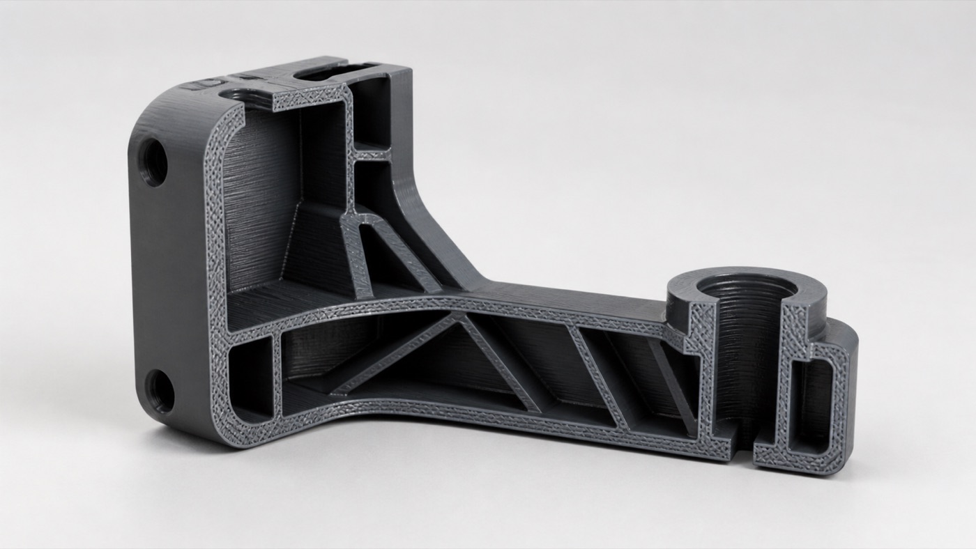
Measure the PCB length, width and thickness, then locate mounting holes. Record the height of the tallest components. Measure connector positions relative to known board edges. Include SD cards, USB plugs, power cables and headers that need to be inserted after assembly.
Step 2: create a component model
You do not need to model every resistor. Create a simplified representation containing the board outline, holes and keep-out volumes for major components. Accurate keep-out geometry makes it easier to design walls and a lid without collisions.
Step 3: choose the mounting strategy
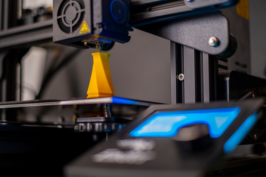
For Arduino, Raspberry Pi and custom PCBs, screw standoffs are common. Add clearance around screw heads and tools. For prototypes that need quick access, slots or clips may work. If the board carries heavy connectors, make sure insertion forces are transferred into the enclosure rather than flexing the PCB.
Step 4: design port openings
Openings should be larger than the connector itself. Real cable housings can be wider and taller. For Raspberry Pi, consider power, HDMI, USB, Ethernet, audio, GPIO and microSD access depending on the model and application. Only expose the ports the product actually needs.
Step 5: plan cooling
A simple microcontroller may need little ventilation, while a single-board computer under sustained load may benefit from airflow, a heatsink or a fan. Do not place vents where dust or liquid exposure creates an unnecessary risk. Thermal design depends on the electronics and operating environment.
Step 6: choose a closure
A two-piece enclosure can use screws, snap fits, sliding rails or magnets. Screws are easy to service and test. Snap fits remove visible hardware but need careful tolerances. Sliding lids can work well for rectangular electronics. Magnets can make frequent access convenient when designed safely around the device.
Step 7: select material
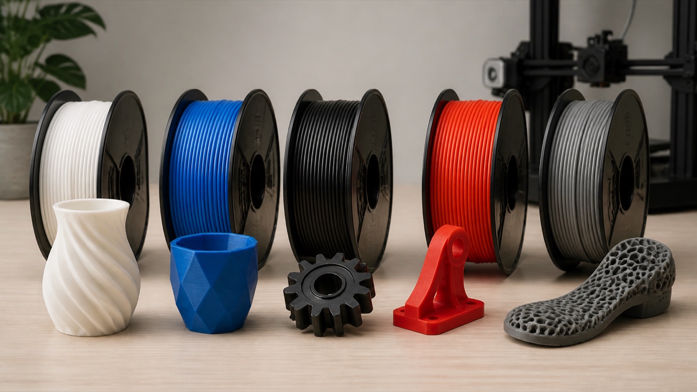
PLA is excellent for many indoor prototypes. PETG provides a useful balance for tougher functional cases. ABS or ASA may be considered for higher temperature or environmental demands. TPU can create protective bumpers or flexible sections rather than the entire rigid enclosure.
Step 8: orient for printing
Design each enclosure half so large flat surfaces can print efficiently and supports are minimized. Chamfers can replace difficult overhangs. Screw bosses should be oriented and reinforced for the expected load. Good print orientation improves finish and can reduce production time.
Step 9: print a fit prototype
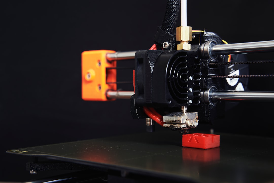
Do not make the first print cosmetically perfect. Use a draft version to verify the PCB, ports, lid and fasteners. Install all cables. If a camera is included, verify its field of view. If a display is included, check readability and button access.
Step 10: revise tolerances
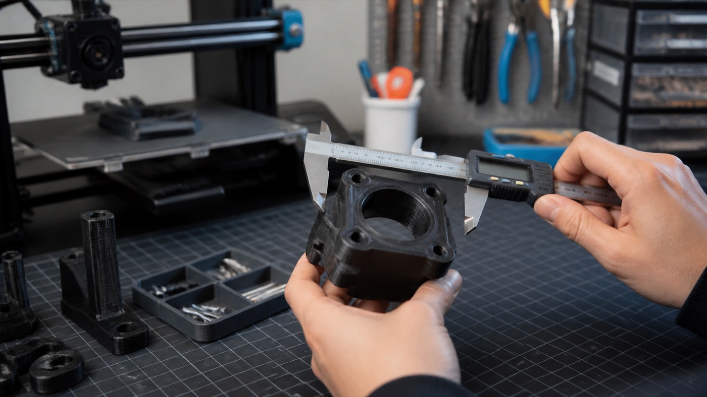
CAD dimensions are not always identical to printed dimensions. Hole size, shrinkage and first-layer behavior can influence fit. Adjust based on the actual print rather than forcing components into an enclosure. Record successful clearances for future designs.
Common mistakes
Frequent problems include forgetting cable heads, blocking the SD card, making screw bosses too thin, leaving no finger access, ignoring heat, placing a seam through a connector and using exact zero-clearance fits. Another common mistake is designing the enclosure before the electronics layout is stable.
When custom design saves time
If your device includes a custom PCB, AI camera, IoT sensor or unusual assembly, building around the real components can be faster than repeatedly modifying generic cases. Artin3D can work from supplied files or, for suitable projects, design an enclosure using client components, measurements and requirements.
Conclusion
A successful 3D printed Arduino, Raspberry Pi or PCB case should feel like part of the device, not an afterthought. Measure accurately, design access around real cables, manage heat and test the first physical version thoroughly. Artin3D – Where ideas take shape.