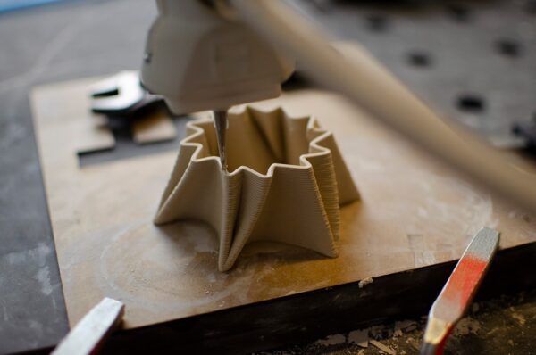
An STL can open normally in a viewer and still cause problems when sliced. Missing surfaces, non-manifold edges, intersecting shells and extremely thin features can create incomplete toolpaths or unexpected repairs. Checking the file before a long print reduces wasted material and troubleshooting time.

What makes an STL printable?
A typical printable model should describe a closed, consistent surface representing the boundary of a solid. Every intended wall needs enough physical thickness for the selected process, and the model should be at the correct scale.
Error 1: holes in the mesh
A gap means the surface does not fully enclose a volume. Repair tools can close simple holes automatically, but large gaps may require manual modeling to preserve the intended shape.
Error 2: non-manifold edges
In a clean closed mesh, an ordinary edge belongs to two faces. Geometry shared in impossible ways can confuse the slicer about which region is inside the object.

Error 3: flipped normals
Mesh faces have an orientation. Inconsistent face normals can make sections appear inside-out in some software. Recalculate or unify normals so the surface direction is consistent.
Error 4: intersecting shells
Two overlapping solids exported as separate intersecting meshes may slice unpredictably. Boolean-union them in the source CAD when they are intended to become one solid.
Error 5: internal faces
Hidden surfaces inside a model can create unnecessary complexity. Remove construction geometry that does not represent the external boundary of the final solid.
Error 6: zero-thickness geometry
A mathematical surface with no thickness cannot become a normal physical wall in FDM or SLA. Give panels and shells a real printable thickness.

Error 7: walls that are too thin
A wall can technically have thickness but still be below the reliable capability of the chosen nozzle, layer strategy or resin process. Review thin features before slicing rather than relying on automatic repair.
Error 8: incorrect scale
STL does not provide a universally reliable unit workflow. Verify the physical dimensions immediately after import. A part intended to be 100 mm long should not arrive as 100 inches or 10 mm.
Error 9: excessive triangle count
A very dense STL can slow software without improving print quality. The mesh only needs enough resolution to represent curves beyond what will be visible in the finished print.
Error 10: coarse tessellation
The opposite problem is visible faceting. If a round CAD surface exports as a polygonal-looking cylinder, return to the source model and use a finer mesh export setting.
Repair in the source CAD when possible
The cleanest solution is often to correct the original solid model and export a new STL. Automatic mesh repair is useful, but it may close a hole in a way the designer did not intend.

Use mesh repair when source CAD is unavailable
Mesh-editing applications can detect boundary edges, fill holes, remove isolated triangles and combine shells. Save a copy before major automated changes so you can compare the repaired geometry.
Check for floating objects
Tiny disconnected triangles or shells may be accidental artifacts. A slicer can attempt to print them in mid-air or generate unexpected toolpaths. Remove any geometry that is not intentionally part of the model.
Check minimum feature size
Text, pins, grooves and embossed logos can disappear when they are smaller than the practical resolution of the process. Preview each layer in the slicer to see whether the intended feature generates toolpaths.
Inspect the first layer
Make sure the model actually contacts the build plate as intended. A nearly flat surface that is slightly tilted can create a tiny first-layer contact and require unnecessary support.
Preview supports
File repair and support planning are different tasks, but both belong to pre-print validation. After the mesh is valid, inspect overhangs and inaccessible cavities.

Check the slicer layer preview
Do not press print immediately after slicing. Move through the layers and look for missing walls, filled openings, unsupported islands and sudden geometry changes. Layer preview is one of the best final checks.
Common symptoms of a damaged STL
- Sections disappear after slicing
- Holes become filled
- Unexpected internal walls appear
- Slicer reports non-manifold geometry
- Thin details vanish
- Part imports at the wrong scale
- Support appears in strange locations
Recommended repair workflow
- Confirm dimensions.
- Run mesh analysis.
- Locate holes and non-manifold areas.
- Remove accidental shells.
- Fix normals.
- Repair or rebuild damaged surfaces.
- Check wall thickness.
- Export a clean copy.
- Slice and inspect layer preview.
- Print a test if the part is critical.
Do not over-repair
Automatic tools can change geometry. After repair, compare critical holes, surfaces and dimensions with the original design. A file that is technically watertight is not useful if a repair tool has closed a functional opening.
When to ask for STEP instead
If a mechanical STL has major problems and the original designer can provide STEP or native CAD, request it. Editing solid geometry is often more reliable than trying to reconstruct a damaged triangle mesh.
Checklist before sending a file to Artin3D
- Correct final size
- Closed printable geometry
- No accidental floating shells
- Appropriate wall thickness
- Curves exported at reasonable resolution
- Important clearances reviewed
- Correct orientation considered
Conclusion
STL repair is not just about making an error message disappear. The objective is to preserve the intended geometry while creating a model that the slicer can interpret consistently. Whenever possible, fix problems in the source CAD, then verify the export with mesh analysis and layer preview. Artin3D can review suitable client files before FDM or SLA production and can provide custom design support where geometry needs reconstruction. Artin3D – Where ideas take shape.