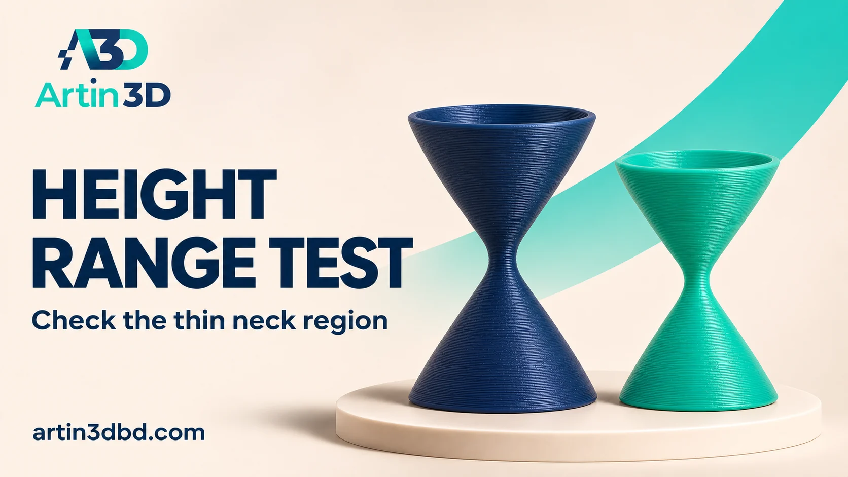
পুরো model ধীর না করে thin neck থাকা height interval এ speed change পরীক্ষা করুন। একই height এর অন্য feature গুলোও পরিবর্তিত হচ্ছে কি না দেখুন।
A display model may have one narrow neck between broader regions. A height range modifier provides a way to investigate a local printing change over that vertical interval. Its scope matters because other geometry at the same height can also be affected. Use a small representative model, inspect the effective paths and keep the supported global profile as the baseline.
Identify the neck’s actual vertical interval
Open the model in its planned orientation and record where the thin region begins and ends. Include the transition into the broader geometry above and below. Save a screenshot showing the intended interval. If another feature shares that height, note it in the test record. A height band is different from a small modifier mesh that intersects only one limited part of the model.
For small feature definition, compare Small FDM Parts Melting? Run a One Part and Four Part Cooling Test and Check Small Perimeter Speed on a Row of Tiny Posts before adjusting multiple speed controls at once.
Save the baseline and add one range
Prusa documents height range modifiers that apply selected settings between defined heights. Use the controls available in your installed version and enter the interval explicitly. Choose one speed related setting supported by the tool for this comparison. Keep layer height, material, fan and other settings unchanged initially. Record the global baseline value and the local candidate so the change can be traced clearly.
Inspect the complete band in Preview
Slice the model and move below, through and above the selected range. Use the speed display to check what changed on the neck and any neighbouring feature. Save matching screenshots for the baseline and candidate. Other motion, cooling or material limits can constrain the effective speed. The result must be visible in the actual generated paths rather than inferred from the presence of a range in the object list.
Print a sample preserving the thin feature
Use a representative model or section that keeps the neck geometry and its transition. Keep the spool, nozzle and plate face identified. After cooling, compare surface appearance, shape and completed print time. Photograph the neck from the same angle for both jobs. Record whether the band introduces a visible surface change at its boundary and whether the broader regions remain acceptable.
Choose the next change from the sample
Keep a candidate only when it improves the required feature without causing an unacceptable change elsewhere. If the problem persists, evaluate cooling, orientation or geometry separately. A slower interval does not repair every thin feature. Save the accepted range and its screenshots in the slicer project. When resizing the model, recheck the interval because its heights no longer necessarily correspond to the same geometry.
Label the scope for the next operator
Record which setting is overridden and which interval contains it. Include a photograph of the accepted boundary appearance. A clear note prevents someone from assuming the entire model uses the visible global speed value. Reopen the saved project and inspect the range before starting a repeat order.
Relevant products from Artin3D
SUNLU PLA Filament 1.75mm
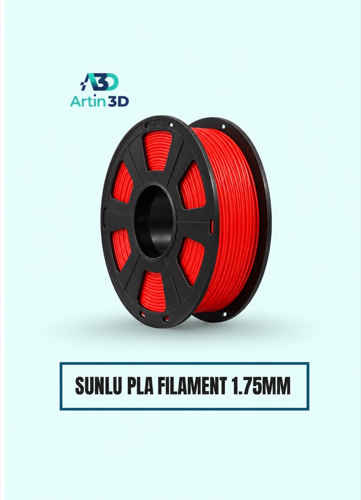
SUNLU PLA is a relevant material for a consistent PLA display sample on a compatible printer. Keep one identified spool throughout the comparison.
SUNLU PLA Matte Filament 1.75mm
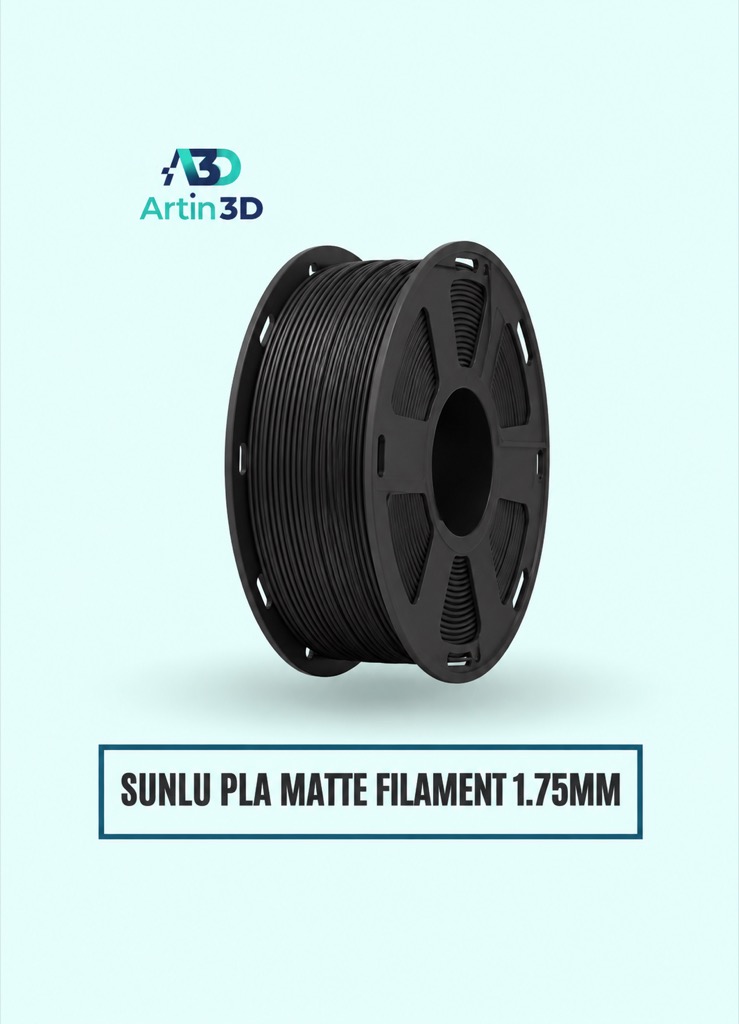
SUNLU PLA Matte can be used for a separate matte finish trial. Confirm the grade and colour and repeat the representative check for the new material.
Quick questions
Does a height range affect only the neck?
Its scope is the selected height interval on the model. Inspect all affected geometry in that band.
Can I keep the same range after resizing?
Recheck the interval and reslice because the feature heights may have changed.
Confirm the exact product variant, printer compatibility, current price and availability on the linked product page before ordering.
Need help preparing a representative sample? Explore Artin3D’s 3D design service or upload your STL file for a 3D printing quote. Include the mating dimensions, intended material and acceptance requirements.