
Cable opening এর fit sample বানাতে slicer এ negative volume ব্যবহার করতে পারেন। Cutout এর মাপ, connector ঢোকানোর জায়গা এবং saved project যাচাই করুন।
A prototype box sometimes needs a trial cable opening before its CAD design is final. A slicer negative volume can help explore a simple cutout in a copy of the model. Treat this as a prototype workflow and inspect the generated paths carefully. The opening must accommodate the relevant connector and assembly route, as well as the cable itself.
Measure the item that must pass through
Identify whether the bare cable, a fixed plug or a strain relief must pass through the opening. Measure the largest relevant section and record how it approaches the wall. Include any movement needed during assembly. Make a small wall sample with the same thickness and orientation as the box. This prevents a promising hole test from ignoring the actual insertion path.
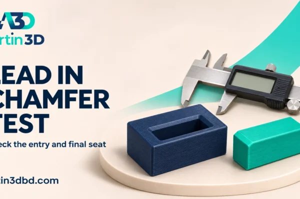
Check the reference dimensions with Check a Bracket Angle and Hole Spacing Before Slicing, and evaluate an entry feature using Test a Lead In Chamfer on a Printed Plug and Socket when it suits the assembly.
Create and position the negative shape
PrusaSlicer provides negative volumes using simple shapes or imported meshes to subtract a region during slicing. Add the shape to a copy of the enclosure and enter its dimensions. Extend it clearly through the wall where the opening is intended. Inspect from inside and outside views. Keep its position recorded relative to a reference surface so later design changes can be checked.
Review the opening layer by layer
Slice the model and move through the cutout from bottom to top. Confirm that the intended region is empty and that surrounding wall paths remain continuous where needed. Check the top of the opening for unsupported geometry. Save a view of the narrowest point and another showing the surrounding wall. A translucent negative shape in the editor is a planning aid, so verify the final toolpaths too.
Print a wall sample and try the assembly route
Use the intended material and allow the sample to cool. Test the connector gently in the same direction required by the enclosure assembly. Record any interference at corners, rounded edges or the wall surface. Measure accessible dimensions and compare them with the design record. Adjust the cutout as a separate revision rather than forcing the component into a sample that does not fit.
Save an editable project and check any exports
Save the slicer project with the negative shape and its position. Reopen it and inspect the opening again. Export behaviour can depend on the application version and export route, so reopen any exported mesh in a separate check before sharing it. For a final engineered enclosure, maintain the approved opening in the source CAD model and document the connector and reference dimensions.
Check the opening’s surrounding edge
An opening can fit the plug yet leave an awkward thin corner or sharp cable contact. Inspect the remaining wall and the cable route after assembly. Revise the prototype geometry when needed, and record which edge treatment was accepted in the final CAD design.
Relevant products from Artin3D
Digital Vernier Caliper
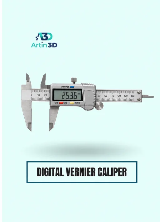
The Digital Vernier Caliper helps measure the connector and the accessible sample opening. Confirm its range and accuracy and keep the reference points consistent.
SUNLU PETG Filament 1.75mm
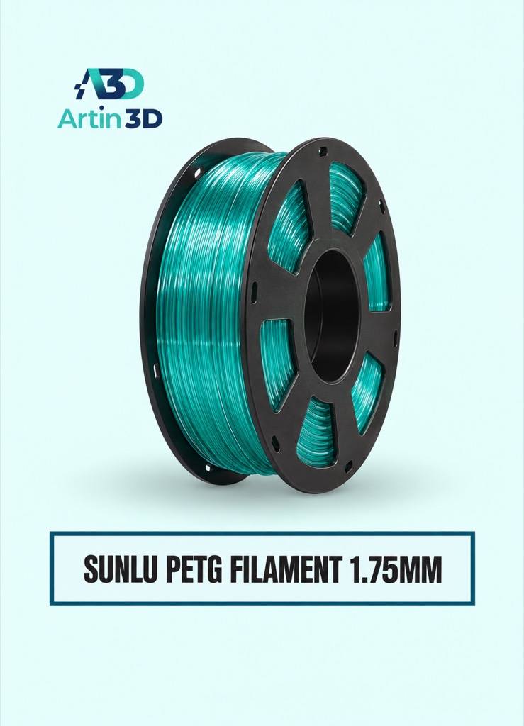
SUNLU PETG can be evaluated for a PETG enclosure sample when its properties suit the intended use. Confirm the exact grade and machine profile.
Quick questions
Should the hole equal the cable diameter?
Measure the connector or strain relief that must pass through, then establish the required fit with a sample.
Does an exported file always preserve the cutout?
Reopen and inspect the exported file. Preserve the editable slicer project and final CAD revision separately.
Confirm the exact product variant, printer compatibility, current price and availability on the linked product page before ordering.
Need help preparing a representative sample? Explore Artin3D’s 3D design service or upload your STL file for a 3D printing quote. Include the mating dimensions, intended material and acceptance requirements.